| 3.3V | 1 | 2 | 5V |
| GPIO 0 | 3 | 4 | - |
| GPIO 1 | 5 | 6 | Ground |
| GPIO 4 | 7 | 8 | UART TX |
| - | 9 | 10 | UART RX |
| GPIO 17 | 11 | 12 | GPIO 18 |
| GPIO 21 | 13 | 14 | - |
| GPIO 22 | 15 | 16 | GPIO 23 |
| - | 17 | 18 | GPIO 24 |
| GPIO 10 | 19 | 20 | - |
| GPIO 9 | 21 | 22 | GPIO 25 |
| GPIO 11 | 23 | 24 | GPIO 8 |
| - | 25 | 26 | GPIO 7 |
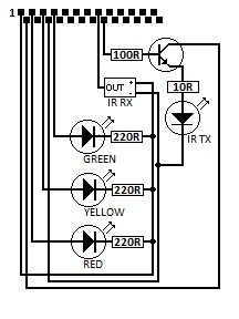
The following describes the current connections used by Elmo.
The LEDs are connected to the GPIO pins and the +ve rail - this means the GPIO must be set low to light the LED, whereas the IR transmitter is connected to the -ve rail so the GPIO must be set high
| Pin | Description | In/Out | Connection |
| 1 | 3.3V | +ve rail. IR Receiver, All LEDs | |
| 2 | 5V | Collector feed for IR TX amplifier | |
| 3 | GPIO 0 | OUT | LED Red via 220 Ohm resistor |
| 5 | GPIO 1 | OUT | LED Yellow via 220 Ohm resistor |
| 6 | Ground | -ve rail. IR Receiver, IR transmitter | |
| 7 | GPIO 4 | OUT | LED Green via 220 Ohm resistor |
| 15 | GPIO 22 | IN | IR Receiver data line |
| 16 | GPIO 23 | OUT | IR Transmitter via 5.5V signal amplifier |
MARK 1. Credit to my Dad for the IR transmitter amplifier circuit